

Limiting rotation 
If we need to limit how far we can rotate a vector to avoid intersections, we could use simple properties of the right triangle:
$$
\Huge\alpha = \arcsin\left(\frac{\text{f@ptdist}}{\text{f@pscale}}\right)
$$
Where f@ptdist is distance to next vector and f@pscale is length of the vector.
matrix3 rot = ident();
float angle = asin(f@ptdist/f@pscale);
angle *= chf("angle_control");
rotate(rot, angle, set(0,0,1));
v@N *= rot;
Dihedral function
A dihedral angle is the angle between two intersecting planes/vectors
$$ \Huge\cos\alpha = \frac{\mathbf{A} \cdot \mathbf{B}}{|\mathbf{A}| |\mathbf{B}|} $$
float cosAngle = dot(B, A) / (length(A) * length(B));
Houdini dihedral function implementation can output matrix3 or quaternion.
matrix3  dihedral(vector a, vector b)
vector4  dihedral(vector a, vector b)
This is done using
float cosAngle = dot(B, A) / (length(A) * length(B));
float Angle = acos(cosAngle);
vector Axis = normalize(cross(B, A));

// matrix construction
matrix3 rotationM = ident();
rotate(rotationM, Angle, Axis);
3@transform = rotationM;

// quaternion construction
p@orient = quaternion(Angle, Axis);
camera frustum
At the time of writing, Houdini does not provide a built-in camera frustum solution, as many VFX studios have their own implementations. I have seen many over-complicated solutions out there, so here is my take on it – simple and effective.
Instead of creating geometry from scratch, we can use existing geometry, like a box, and modify it into a frustum shape. We can utilise the NDC (Normalised Device Coordinates) function for this, by pretending that our incoming geometry is within the NDC space, and then converting it back to world space.
What is NDC? Normalized Device Coordinates (NDC) is a coordinate system that standardizes the range of values for object coordinates. In NDC space:
The x and y coordinates range from -1 to 1. The z coordinate ranges from 0 (near plane) to 1 (far plane). This normalisation allows for easy manipulation and transformation of objects within a predictable space.
string cam = chs("camera");

// normalize scale
v@P /= getbbox_size(0);

// overscan
float over = chf("overscan");
v@P *= set(over, over, 1);

// normalize position
v@P += set(0.5, 0.5, -0.5);

// near/far clipping
float near, far;
if(chi("read_from_camera")){
    near = chf(cam+"/near");
    far = chf(cam+"/far");
}else{
    near = chf("near");
    far = chf("far");
}
v@P.z *= far-near;
v@P.z -= near;

// build frustum
v@P = fromNDC(cam, v@P);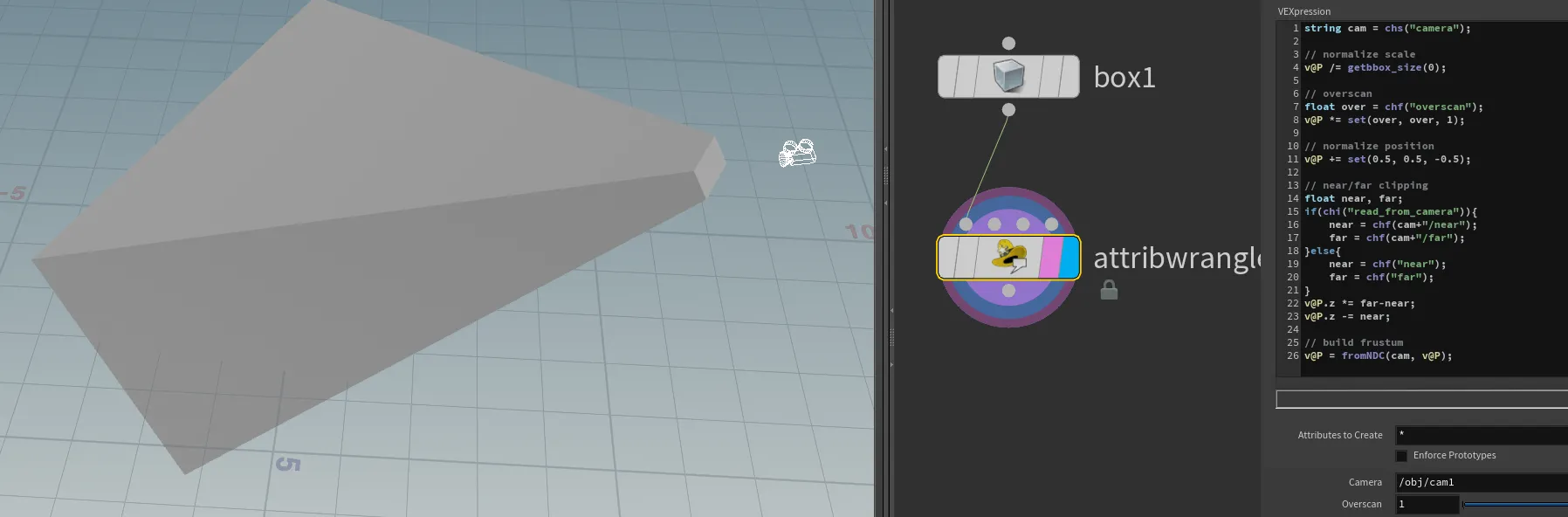
SOP Caustics
Following our cop-caustics implementation, here is a a SOP version.
Similar to how water 'lensing' focuses rays of light, we are 'sliding' our points (rays of light) by the slope of a noise function (in this case, simplex noise).
UPDATE!
Sidefx included vex function xnoised which already provides us with a gradient (slope/derivative) output. This simplifies everything to just one function
float frequency = chf("frequency"); // 5
float focus = chf("focus")/frequency; //0.3
float speed = chf("speed"); // 0.2
vector dir; float n;
vector uv = v@P;
uv.y = @Time*speed;
xnoised(uv*frequency, n, dir.x, dir.y, dir.z);

v@P+= dir*focus*{1,0,1};
v@Cd = clamp(pow(n, 5)*5, 0, 1);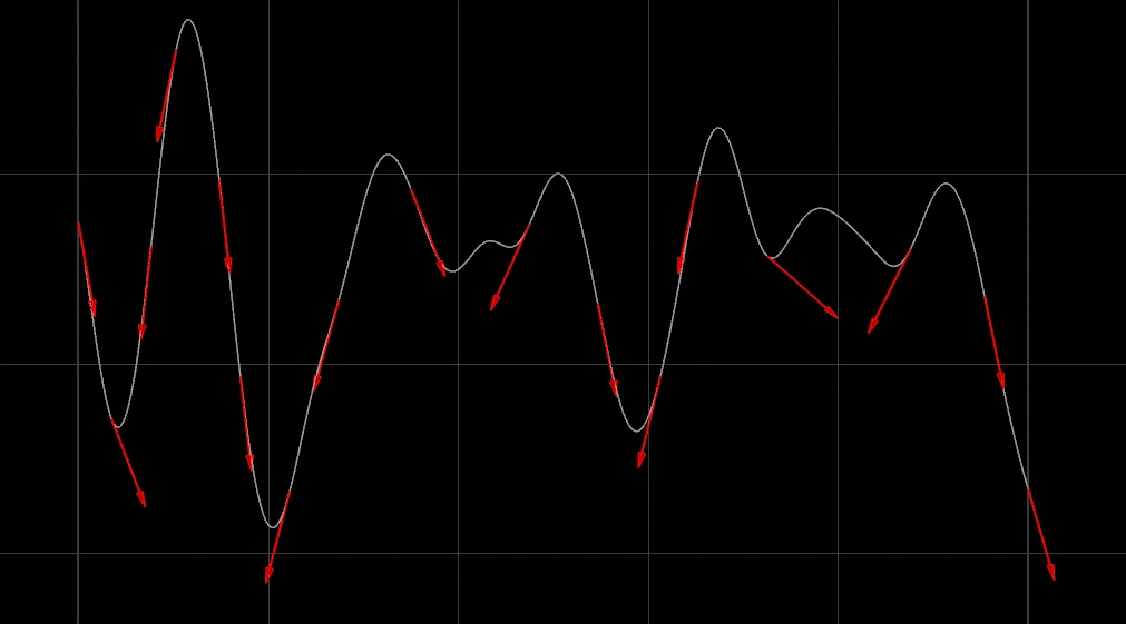
Lights In VEX
This is a simple concept that has been utilized in a few big VFX productions where we wanted to avoid expensive light rendering. Imagine lightning in the clouds or hundreds of street/neon lights in a vast city. Such scenarios could become very heavy for the renderer. While baking light into a texture is not a new idea, how can we bake light into a volume?

Math and VEX to the rescue! The idea is quite simple - we do exactly the same math as the renderer but using our VEX skills.
Light Decay
First, we want to calculate light decay. Depending on the medium, we can apply different techniques here. The most popular would be to calculate light decay using the (Inverse-square law](https://en.wikipedia.org/wiki/Inverse-square_law).
The inverse-square law states that the intensity of light radiating from a point source is inversely proportional to the square of the distance from the source. The formula is: $$ \Huge\ I = \frac{P}{d^2} $$ where $I$ is the intensity, $P$ is the power of the light, and $d$ is the distance from the light source.
light_decay = (1 / (light_dist*light_dist))*light_power;Another popular decay model we might want to apply here is the Beer-Lambert law , which describes how light is absorbed and scattered as it travels through a medium.
The Beer-Lambert law is given by: $$ \Huge\ I = I_0 \cdot e^{-\alpha d} $$
where $I$ is the transmitted intensity, $I_0$ is the initial intensity, $\alpha$ is the absorption coefficient, and $d$ is the distance through the medium.
Shading
When light hits a surface, it gets reflected. The way light gets reflected depends on the surface type itself. The simplest reflectance calculation is Lambertian reflectance , which defines an ideal "matte" or diffusely reflecting surface.
The Lambertian reflectance is given by:
$$ \Huge\ L \cdot N = |N||L| \cos(\alpha) = \cos(\alpha) $$
where $L$ is the direction of the incoming light, $N$ is the normal to the surface, and $\alpha$ is the angle between $L$ and $N$.
lambert = max(0, dot(normalize(v@N),normalize(light_dir)));Light accumulation
Once we calculate everything, we should accumulate our light and apply color.
v@lout += light_color*(light_decay/no_lights)*lambert;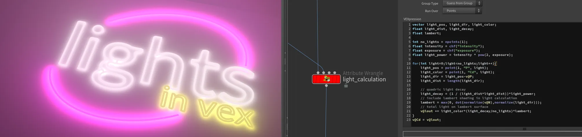
Calculating light for the volume is even simpler as we can skip reflectance model entirely!
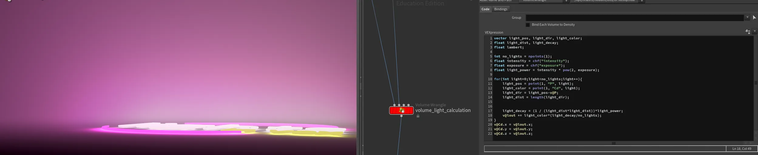
WARNING: This provided scene file is not production ready! - Its not optimised (it is a brute-force loop over every point/light which also makes light accumulation not very precise) in a scene and it is just a prove of concept.
Pscale by the camera
In some situations, it might be handy to have the point scale remain consistent, no matter the distance from the camera. This can be achieved using a simple algebraic approach to calculate the size of a pixel in world space:
$$ \text{Pixel Size} = \left(\frac{\text{Aperture}}{\text{Focal Length}}\right) \times \left(\frac{\text{Distance}}{\text{Resolution}}\right) $$
This formula is derived from fundamental principles of camera optics:
- Aperture: The physical size of the lens opening, which controls the amount of light entering the camera. It affects the field of view and depth of field.
- Focal Length: The distance between the lens and the image sensor when the subject is in focus. It determines the magnification and angle of view.
- Resolution: The number of pixels across the image sensor. Higher resolution means smaller pixel size for the same sensor size.
- Distance: The distance from the camera to the point in world space.
This formula calculates the projected size of a pixel at a given distance from the camera, considering the camera's optical properties (aperture and focal length) and the image resolution. This ensures that the point scale remains consistent, regardless of its distance from the camera.
You can easily obtain aperture, focal length, and resolution from the camera/renderer info. The distance (Pz) can be obtained in a few ways:
- Using uvtexture and mapping your geometry with "perspective From Camera" to extract the Z value.
- Calculating NDC space and extracting the Z value.
- Projecting P-cam onto cam.z. You can read more about projections here
string cam = chs("camera");
float apert = chf(cam + "/aperture");
float focal = chf(cam + "/focal");
int resx = chi(cam + "/resx");
float pixsize = apert / focal;
vector Pndc = toNDC(cam, v@P);
float Pz = max(0, -Pndc.z);

// pscale size of pixel (based on camera RESOLUTION)
f@pscale = pixsize * (Pz/resx);

// adjust unified pscale by user input
f@pscale *= ch("pscale_multi");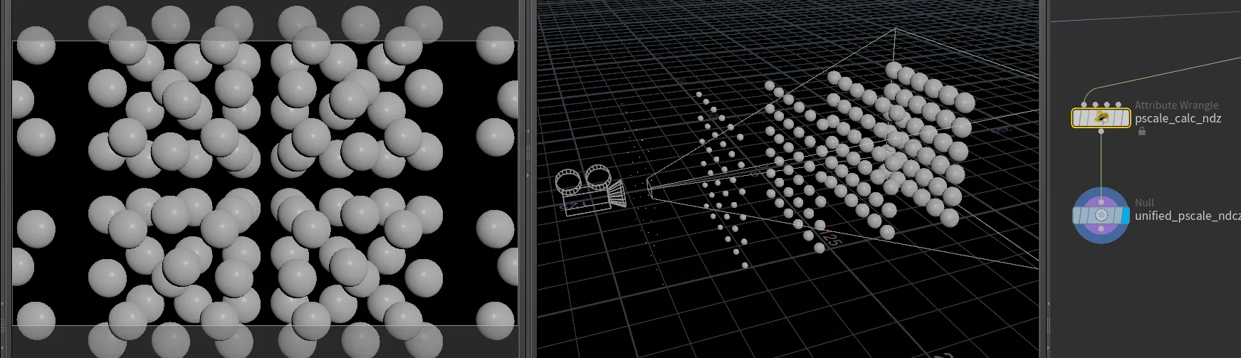
Vector projections
Vector projections sop-dot-projection
Vector projection is a powerful tool in VFX and 3D graphics, allowing us to determine how much of one vector "shadows" or projects onto another vector. This can be useful in a variety of contexts, such as aligning objects, calculating forces, or understanding the relationship between different vectors in space.
The formula for vector projection is:
$$ \huge\mathbf{c} = (\mathbf{a} \cdot \hat{\mathbf{b}}) \hat{\mathbf{b}} $$
vector c = dot(a, normalize(b)) * normalize(b);
Swirl Effect on Geometry and Volumes
Swirl effects are quite typical in the FX world. Whether you're new to Houdini or a seasoned pro, this guide will show you how to create a simple yet powerful swirl effect using VEX. We'll apply a rotational transformation to achieve this effect on both geometry and volume data.
Swirling Geometry
First, let's look at how to apply a swirl effect to geometry. We will use a rotation matrix to rotate the points around a specified center. Here's the VEX code you'll need:
vector center = point(3, "P", 0);

float mask = chramp("mask_falloff", fit(length(center-v@P), 0, chf("max_dist"), 1, 0));

matrix3 rot = ident();
float angle = chf("angle")*mask;
rotate(rot, angle , chv("axis"));

v@P -= center;
v@P *= rot;
v@P += center;Explanation:
- Center Calculation: We start by specifying the center of the swirl effect.
- Distance Mask: A mask is created to control the intensity of the swirl based on the distance from the center. The chramp function allows for artistic control over the mask.
- Rotation Matrix: A rotation matrix is created and the rotation angle is determined by the mask. The geometry is then rotated around the specified axis.
- Transform Geometry: To apply the rotation correctly, we temporarily move the geometry to the origin, apply the rotation, and then move it back.
Swirling Volumes
The same setup can be utilized for volumes. However, since we cannot directly move voxels, we'll copy them into a new layer from a new position.
of course, same setup could be utilised for other elements like volumes. One thing to note here - we cannot move voxels (its like pixels in 3D space), but we can copy them into a new layer from a new position:
vector center = point(3, "P", 0);

float mask = chramp("mask_falloff", fit(length(center-v@P), 0, chf("max_dist"), 1, 0));

matrix3 rot = ident();
float angle = chf("angle")*mask;
rotate(rot, angle , chv("axis"));

vector pos = v@P;
pos -= center;
pos *= rot;
pos+= center;

f@density = volumesample(1, 0, pos);Explanation:
- Center Calculation: Similar to the geometry, we start by specifying the center of the swirl effect.
- Distance Mask: A mask is created to control the intensity of the swirl based on the distance from the center.
- Rotation Matrix: A rotation matrix is created and the rotation angle is determined by the mask.
- Transform Volume: The new position for each voxel is calculated by temporarily moving the position to the origin, applying the rotation, and then moving it back. The voxel data is then sampled from the original volume at this new position.
By understanding and utilising these techniques, you can create stunning swirl effects in your Houdini projects. Happy swirling!
Alligator Noise
Provided VEX function already gives us most of the options that you are used to see in vops.
float  anoise(vector pos)
vector  anoise(vector pos)
float  anoise(vector pos, int turbulence, float rough, float atten)
vector  anoise(vector pos, int turbulence, float rough, float atten)
float  anoise(vector pos, int periodX, int periodY, int periodZ)
vector  anoise(vector pos, int periodX, int periodY, int periodZ)
float  anoise(vector pos, int periodX, int periodY, int periodZ, int turbulence, float rough, float atten)
vector  anoise(vector pos, int periodX, int periodY, int periodZ, int turbulence, float rough, float atten)
Missing part is frequency, offset and amplitude.
Frequency is just a scale factor of incoming value, so we can simply multiply input the input.
Offset is shifting out input, therefore we can just add or subtract it. To match VOP behaviour, we should use subtract.
Amplitude is total scale of the output noise, so simple multiplication will do the trick.
Here is a code matching same behaviour as VOP counterpart:
vector pos = v@P;
vector frequency = chv("Frequency");// default (1,1,1)
vector offset = chv("Offset");// default (0,0,0)
int turbulence = chi("Turbulence");// default 5
float rough = chf("Roughness");// default 0.5
float atten = chf("Attenuation");// default 1
float amplitude = chf("Amplitude");// default 1

vector alligator = anoise((pos*frequency)-offset, turbulence,  rough, atten);
alligator *= amplitude;
v@P += alligator;